Hot Water From The Sun’S Rays
pp. 49-71 · Read in the full issue
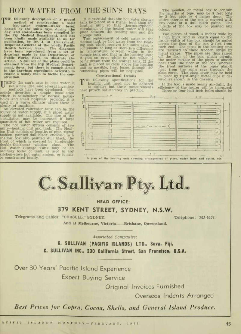
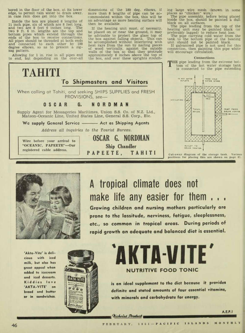
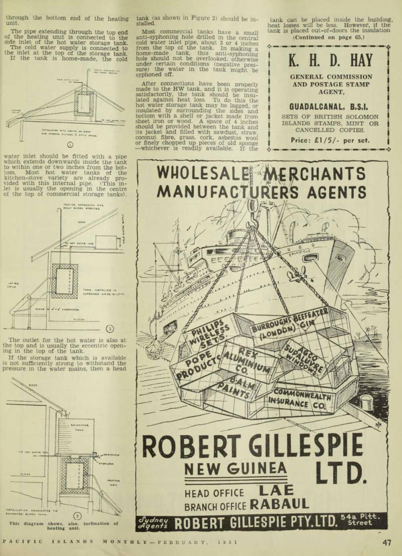
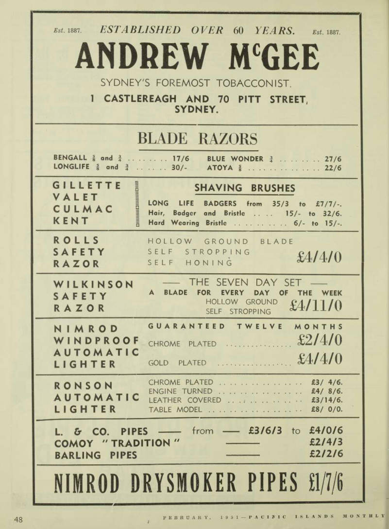
THE following description of a proved method of constructing a solar hot-water system—water being heated by the sun’s rays, during the day, and stored—has been compiled by the Fiji Medical Department, and has been kindly made available to us, for publication, by Dr. J. M. Cruikshank, Inspector-General of the South Pacific Health Service, Suva. The diagrams have been reproduced from a set of drawings made by the Department of Public Works, Suva, to illustrate the article. A full set of the plans could be obtained from the Fiji Medical Depart ment, Suva; but there is enough detail in the drawings reproduced herewith to enable a handy man to tackle the con struction.
USING the sun’s rays to heat water is not a new idea, and several ingenious methods have been developed. This article describes a simple installation which is satisfactory for normal house holds and small hospitals, provided it is used in a warm climate where there is plenty of sunshine.
An elevated rainwater tank can be the source of water supply, if a piped water supply is not available. The size of the installation may be increased if large quantities of hot water are required.
The hot water system consists of two units —heating unit and tank. The Heat ing Unit consists of lengths of pipe, zigzag fashion, painted dull black, enclosed in a shallow box also painted dull black, the front of which is covered by (preferably double-thickness) window glass. The Hot Water Storage Tank may be an ordinary boiler or tank, as used in any kitchen-stove hot water system, or it may be constructed locally.
It is essential that the hot water storage tank be placed at a higher level than the heating unit, so that thermo-syphonic circulation of the heated water will take place between the heating unit and the storage tank.
This replacement of cold water in the storage tank by hot water from the heat ing unit which receives the sun’s rays, is continuous, so long as there is a difference in temperature between water in the storage tank and that in the heating unit; it goes on even while no hot water is being drawn from the storage tank. If the tank is placed as close above the heating unit as possible, heat losses through the connecting pipes will be negligible.
Constructional Details THE following specifications for the heating unit need not be adhered to rigidly; but these measurements have proven satisfactory in practice.
The wooden, or metal box to contain the lengths of pipe, may be 9 feet long by 3 feet wide by 4 inches deep. The entire interior of the box is covered with two coats of a dull black paint. The outside of the box may be painted any colour.
Two pieces of wood, 4 inches wide by 1 inch thick, and in length equal to the inside width of the box, should be nailed across the floor of the box 2 feet from each end. The pipes in the heating unit are fastened to these wooden strips by metal straps. The pipes are thus raised off the floor of the box, which permits the under surface of the pipes to absorb heat from the floor of the box, whereas the front surfaces of the pipes absorb heat from the sun’s rays through the glass cover. The glass cover may be held in place by right-angle metal clips if de sired as shown in the drawing.
If the box is made nearly air-tight, the efficiency of the heater will be increased.
Three or four half-inch holes should be
A plan of the heating unit showing arrangement of pipes, water inlet and outlet, etc.
bored in the floor of the box, at its lower edge, to permit rain water to drain away, in case rain does get into the box.
Inside the box are placed 8 lengths of II inch pipe, six of which are 8 feet long, and two are 9 feet 6 inches long. The two 9 ft. 6 in. lengths are the top and bottom pipes which extend through the ends of the box to receive connections.
All pipes should be threaded at both ends and connected to each other by 180 degree elbows, so as to present a zig zag pattern.
Allowing for 1 in. rise in all pipes end to end, but depending on the over-all
dimensions of the 180 deg. elbows, if more than 8 lengths of pipe can be ac commodated within the box, this will be an advantage as more heating surface will then be available.
If the heating unit must, of necessity, be placed on or near the ground, it may be advisable to protect the glass top of the box against falling objects. This can be accomplished without interfering with heat rays from the sun by nailing pieces of wood vertically, against the outside walls of the box so that they protrude approximately 8 inches above the top of the box, and over these uprights stretch
ing large wire mesh (known in some places as “chicken” wire.) The pipe assembly, before being placed inside the box, should be painted a dull black on all surfaces.
The pipe leading from the top of the heating unit may be painted black (or preferably lagged) to reduce heat loss.
The pipe carrying cold water from the tank to the bottom pipe of the heating unit should not be painted black.
If galvanised pipe is not used for this connection, then painting this pipe white will encourage circulation.
Connections THE pipe leading from the extreme bot tom of the hot water storage tank is connected to the pipe extending
Cut-away diagram of the storage tank. Various positions for placing this are shown on page 47.
through the bottom end of the heating unit.
The pipe extending through the top end of the heating unit is connected to the side inlet of the hot water storage tank.
The cold water supply is connected to the inlet at the top of the storage tank.
If the tank is home-made, the cold
water inlet should be fitted with a pipe which extends downwards inside the tank to within one or two inches from the bot tom. Most hot water tanks of the kitchen-stove variety are already pro vided with this internal pipe. (This in let is usually the opening in the centre of the top of commercial storage tanks).
The outlet for the hot water is also at the top and is usually the eccentric open ing in the top of the tank.
If the storage tank which is available is not sufficiently strong to withstand the pressure in the water mains, then a head
tank (as shown in Figure 2) should be in stalled.
Most commercial tanks have a small anti-syphoning hole drilled in the central cold water inlet pipe, about 3 or 4 inches from the top of the tank, in making a home-made tank, this anti-syphoning hole should not be overlooked, otherwise under certain conditions (negative pres sure) the water in the tank might be
syphoned off.
After connections have been properly made to the HW tank, and it is operating satisfactorily, the tank should be insu lated against heat loss. To do this the hot water storage tank may be lagged, or insulated by surrounding the sides and bottom with a shell or jacket made from sheet iron or wood. A space of 4 inches should be provided between the tank and its jacket and filled with sawdust, straw, coconut fibre, grass, cork, asbestos wool or finely chopped up pieces of old sponge —whichever is readily available. If the
tank carl be placed inside the building heat losses will be less. However 1 , if the tank is placed out-of-doors the insulation
(Continued on page 65.)
This diagram shows, also, inclination of heating unit.
on the top should be protected against rain, and the jacket painted black.
Provided the tank is well insulated, the water will remain hot from 24 to 36 hours, if sunny weather is followed by overcast or cloudy weather, depending of course upon the quantity of water drawn off.
Practical installations are represented in the various sketches, all of which have worked satisfactorily.
The heating unit described is suitable for a tank with a capacity of 40 to 80 gallons, depending on the quantity of hot water required.
Installation THE heating unit should be placed on the sunniest aspect of the building, so as to receive maximum duration of radiation from the sun, and should be inclined from the vertical to enable the heated water to rise to the storage tank and at the same time receive the maxi mum of direct rays from the sun. (See Fig. 3, page 65.) Apart from producing hot water for bathing and laundry purposes, this in stallation can be used to pre-heat water for a steam boiler; or the heating unit can be connected to an existing tank, containing either a manually-controlled or a thermostatically-controlled heating element. If automatically controlled, the thermostat is activated and electric power is used only if the temperature of the water, due to prolonged cloudy weather, falls below the temperature pre sent on the thermostat. It is surprising, even during lightly overcast weather, the amount of infra red rays absorbed by the heating unit.
In the writer’s experience, the highest water temperature is reached about 2 p.m.
The following record of temperatures may be of interest, even though normal quan tities of hot water were drawn off during the day:— 2 p.m.—Cold water temp. 90 deg. Fahr.
Hot water temp. 126 deg.
Air Shade temp. 87 deg. 9 p.m.—Cold water temp. 91 deg. Fahr.
Hot water temp. 118 deg.
Air Shade temp. 82 deg.
8 a.m.—Cold water temp. 82 deg.
Hot water temp. 100 deg.
Air Shade temp. 82 deg.
The essential features are:— 1. —A heating unit consisting of:— (a) a box painted dull black inside, (b) zig-zag lengths of pipe painted dull black, within the box. (c) a transparent glass cover on the box. 2. —A hot water storage tank which
must be raised above the level of the top of the heating unit.
Bill of Materials 2—pieces 10 ft. x 4 ft. x 2 in.—sides of box. 9—pieces 10 ft. x 4 in. x 1 in.—bottom of box. 2—pieces 2 ft. 8 in. x 4 in. x 2 in.—ends of box. 2—pieces 2 ft, 8 in. x 4 in. x 1 in.—strips for floor of box. 4—pieces 2 ft. 8 in. x 2 in. x 1 in.—strips to support glass top of box. 6 II in. iron or copper pipes 8 ft. long. 2—II in. iron or copper pipes 9 ft. 6 in. long. 16—II in. pipe clamps or metal strapping. 7 14 in. 180 deg. elbows. 2—II in. 90 deg. elbows. (Or tees with a plug in one opening. This arrange ment facilitates draining of the heat ing unit and tank, if desired.) 2—II in. union couplings for connecting pipes.
I—4o-80 gallon tank.
Window glass sufficient to cover front of box.
Dull black paint sufficient for two coats.
Sufficient galvanised clips to hold glass cover in place.
Mr. A. H. Davies has arrived in Fiji to take over the managership of the Suva branch of the Bank of New South Wales.
The previous Manager was Mr. W. F.
Hargreaves, who has been transferred to New Zealand.
Although they are gradually declining in number since the war, British residents are still the most numerous of New Caledonia’s foreign element. Out of 378 foreigners in 1950, 166 were British, a recent count reveals.