Handy Type Of Copra Drier
pp. 30-32 · Read in the full issue
By C. Falkner, of Tearouki Plantation, Tiop, New Guinea.
I SEND you herewith a description of a cheap hot-air drier. I have been using it on my own plantation for the last eight months and found it most effective.
Cheapness, of course, especially in these days, is the first consideration, and the cost of this type is about £40. It Is simple to operate, and it is practically fireproof, as no vulnerable part is exposed to the fire.
The copra turned out is pure white, and has been extremely well commented on by the copra inspectors here.
I am forwarding it to you, hoping that it may be of some use to the smaller planters, to whom, as in my case, an in expensive but effective hot air drier means
the all-important factor of those few extra shillings per ton.
The drawings are not as clear as I should like, but I think any copra man will be able to follow them.
With the best wishes to your much
valued journal.
Half Ton Kiln Drier
Dimensions: Length of bed, 24 feet.
Width of bed, 12 feet.
Height above ground, 3 feet.
The drier consists of a timbered frame, on the inside of which 26 gauge flat iron is nailed in such manner as to make it smokeproof.
Erecting
An outside shelter, consisting of roof only, 36 x 24 feet, is first constructed.
Then a concrete foundation for the bed, 9 x 4in. (6in. into the ground) into which the upright posts are set, 3 feet apart. These may be made of any native hardwood, squared on two sides.
The last two panels, i.e., 6 feet on each side, as well as the whole of the firepit end, are made entirely of concrete —sunk 3 feet into the ground, and 3 feet above, with a 4 feet wide tunnel, 2 feet long, forming entrance to the firepit and ensuring a draught. An outside pit 4x4 feet is advisable to enable a free flow of air to the tunnel, see figures 1 and 2. .
Next the uprights are connected with timber 3 x 3in., reaching right round, on which the bearers of 3 x 4in. are placed, across the bed, 18in. apart. These are nailed in the middle to a length of native timber shaped to 12 x 6in. running lengthways across the drier, to support the bearers.
This beam lies on top of the bearers.
Flat iron sheets are nailed on, underneath the bearers, care being taken to prevent any opening where smoke can come through.
NOTE: The exact width is made 11ft. 10in. to allow a 1in. turn over of the iron on each side of the bed, to make an overlap with the upright iron on the sides.
The sides are now enclosed with sheet iron ire the same manner as above; the height from con-
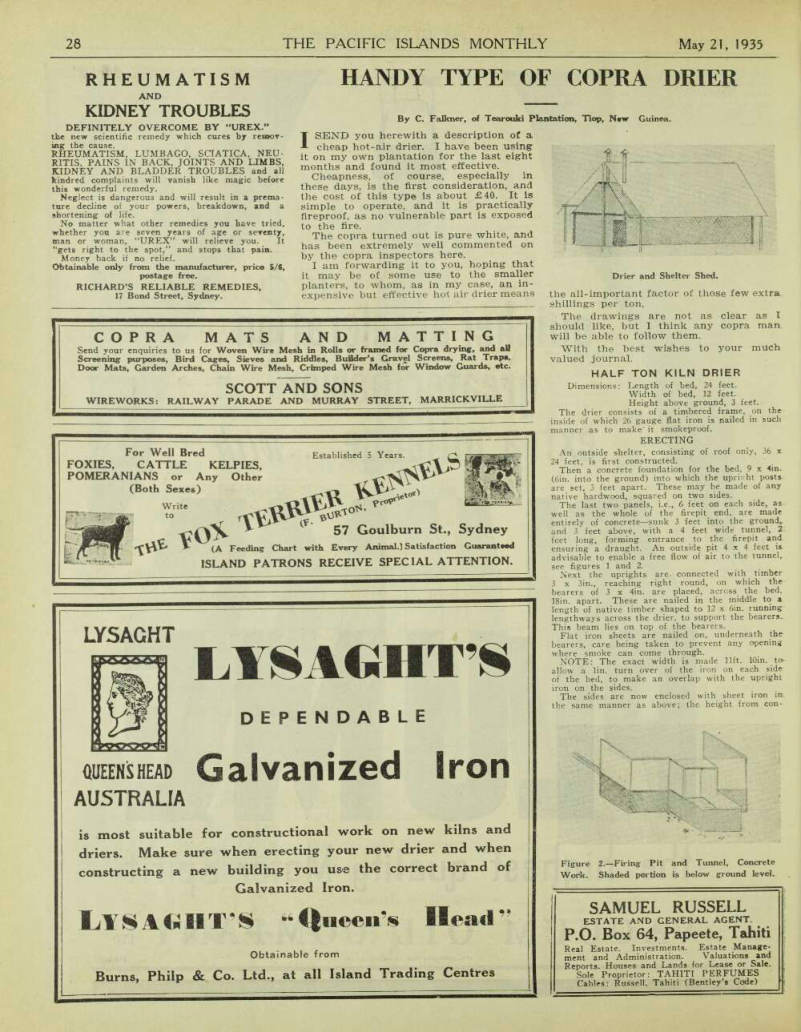
Figure 2.—Firing Pit and Tunnel, Concrete Work. Shaded portion is below ground level.
Drier and Shelter Shed.
crete foundation to bearers being made 2ft. 11in., allowing for a 1in. overlap with the roof iron.
On top of the bearers mesh wirenetting is fastened (fig. 3).
Two smokestacks, made of flat iron (6 x 3ft.) are placed 18in. from the end and equidistant from the sides and each other, i.e., 4 feet from the side to the centre of the smokestack.
At the firing end, the ground is excavated to a depth of 3 feet and the ground removed thrown towards the other end, forming a sloping bank up to 18in. from the iron roof (see fig. 4).
Over the whole, a house is built (inside the shelter shed), leaving 3 feet room on the sides, 4 feet in front and 2 feet at firing end, bringing rear wall flush with end of the firing tunnel.
Walls are made of platted bamboo, lined with native thatch. Roof of native thatch, leaving
Figure 5. —Ground Plan of Layout. 3 feet open at the ridge, the whole length of the house, to enable rapid exit of the saturated air.
There should be at least 3 feet clearance between the roof of the drier and the roof of the shelter shed.
At 6 foot intervals, air inlets, 4 x 4in., are pro vided at the bottom of the side walls.
The smokestacks must go at least 5 feet above the ridge of the outer roof.
Eighteen inches above the copra bed “second day” shelves are built of 3 x 2in. framing, 3 feet wide, covered with wirenetting. One on each side and running the whole length of the bed.
Operation
The capacity of the drier is 3000 nuts, every 24 hours. The nuts are collected and carried to a husking shed, alongside the drier, where they are husked and placed in readiness close to the door. One boy can, after a little practice, husk 800 nuts per day as well as assist with the operating of the dried.
First Day Fire is lighted in the drier the night before and from then on is not extinguished or lessened until for some reason or other copra cooking is dis continued. The filling up, periodical examination and removal of dried copra may be carried out with full firing going on, thereby eliminating the loss of time in waiting for fires to cool off and of relighting.
At 6 a.m. the drier is filled by taking the husked nuts, breaking them in halves and lining them on the wire in a three-quarter upright position, each leaning against the other, meat down. This economises space and ensures thorough circulation.
If the half nuts are placed flat, meat down, dis-
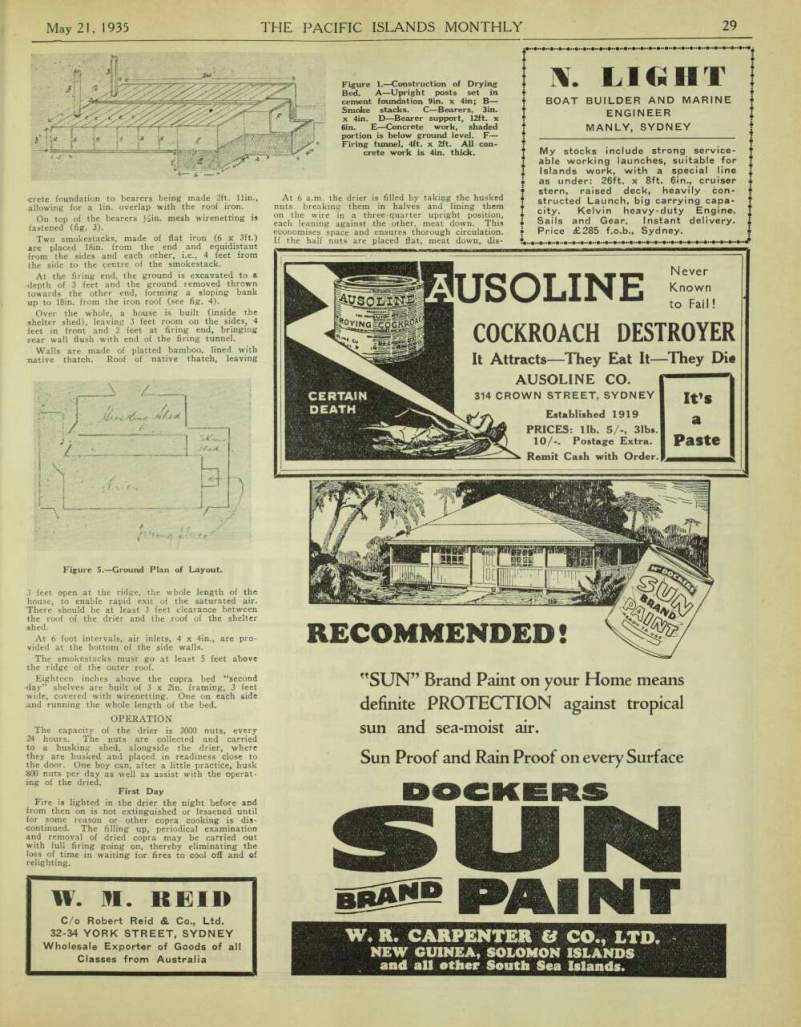
Figure 1. —Construction of Drying Bed. A—Upright posts set in cement foundation 9in. x 4in; B— Smoke stacks. C—Bearers, 3in. x 4in. D —Bearer support, 12ft. x 6in. E—Concrete work, shaded portion is below ground level. F— Firing tunnel, 4ft. x 2ft. All con crete work is 4in. thick.
colouration of the copra results, owing to insuffi cient circulation of air. Another point to note is that the meat is not exposed to the air until placed on to the already heated bed.
This work is done by the four huskers and two of the three firemen.
At 6 p.m. the copra will be found half-dried and so loose in the shell that a smart tap on the back of the half-nut will cause it to drop out. The shell removed, the copra is thrown back on to the wire bed, anyhow.
Second Day At 6 a.m. the half nuts are heaped on to the “second-day” shelves and the drier refilled.
At 6 p.m. the shell from the second lot of copra is removed.
Third Day At 6 a.m. the first lot of half nuts are removed from the “second-day” shelves and taken to the copra shed. The second lot of nuts arc placed up on to the shelves and the drier refilled again.
Firing: Shells and husks are used, half and half.
Labour
Eight units are employed to carry nuts to the drier every day, each 300. (When areas close to the drier are worked, the task is increased.)
Weeding gangs and other units on field work bring in 20 nuts each every avening.
Saturdays as many units as neces sary bring in 200 nuts each.
Three firemen are used, working four-hour shifts, from 6 p.m. All three are on duty at 6 p.m., and with the four huskers remove the shell.
At 6 a.m., two firemen, those from 6 to 10 p.m. and 2 to 6 a.m. shifts are available with the four huskers to remove the dried copra, shift up to “second-day” shelves, and refill the drier. This operation takes from 2 to 2½ hours.
Material Required
Material needed; 46 sheets flat iron, 26 gauge. 12 packets clouts. 6 packets roofing nails (for use on
iron forming roof of bed, as with the con traction of the iron from the heat, the clouts in the centre pull out). 240 feet 3 x 4in. hardwood. 120 feet of 3 x 2in. hardwood. 4 casks cement.
The remainder may, if desired, be made from native timber.
Advantages
Cheapness of construction.
Simpleness of operation.
Fire-proof.
First-class copra.
Even heat maintained and copra not exposed to. air until placed on to bed.
The above drier is turning out a pure white type of dried copra, which keeps well. No copra is lost in cutting or in small pieces falling through the wire in drying.
NOTE: In firing, the most important factor is a small but even fire. I have found that if five half-shells are cupped together, thrown on the fire, followed by approximately double that amount of husks, a fire sufficient for effective heating can be maintained.
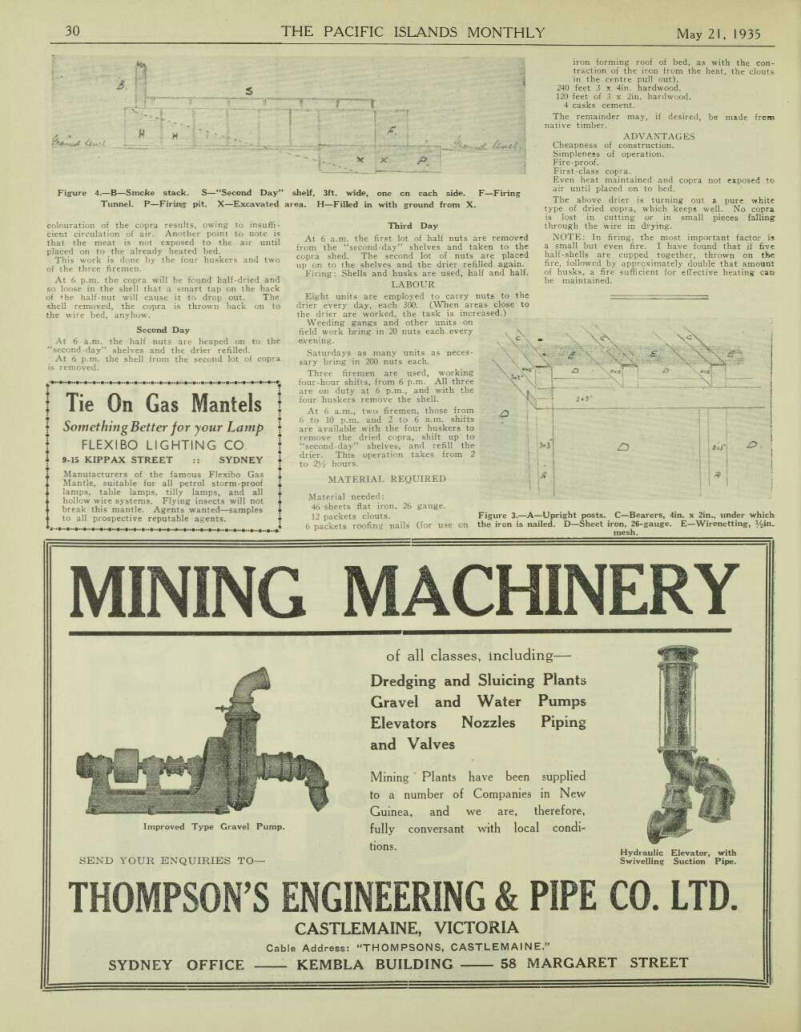
Figure 4.—B—Smoke stack. S—“Second Day” shelf, 3ft. wide, one on each side. F—Firing Tunnel. P—Firing pit. X—Excavated area. H—Filled in with ground from X.
Figure 3.—A—Upright posts. C—Bearers, 4in. x 2in., under which the iron is nailed. D—Sheet iron, 26-gauge. E—Wirenetting, ½in. mesh.