How To Use Your Water Power
pp. 79-82 · Read in the full issue


In all the high islands of the Pacific, countless millions of horse-power are running to waste, because no attempt is made to harness the mountain streams. In the following article, written by Bert Wilson and published in the well-known technical journal, Power Farming in Australia and New Zealand, the Islands resident is shown how he can make use of the water-power avail able to him.
IHE electrical blackouts we are at present experienc ing in the country districts of NSW have resulted in a lot of inquiries regarding the possibilities using a flow of water to provide power to generate jctricity.
To obtain power from water you require either a I flow of water from a low head or a smaller flow 3m a high head, for as with all calculations con rning power it all boils down to the foot-pounds work which the water can produce. It is all a it ter of gravity; most water-engines are simply avity motors. For instance, if the available flow ls, say, 600 gallons per minute and the head or fall y, 10 ft., the power produced would be 60,000 foot unds per minute (600 x 10 (lbs per gall) x 10 = 000). By the same token a flow of 100 gallons per nute with a fall of 60 ft would produce the same lount of work (100 x 10 (lb per gal.) x 60 = 60,000).
You will remember that theoretically 33,000 foot unds of work per minute is required to produce hp, so (again theoretically) either of the proposi ns mentioned above would produce just under 2 hp. ifortunately, however, the factor which makes per tual motion impossible—namely, loss of efficiency— s to be taken into consideration. No machine is ) per cent, efficient. In other words the energy produces is less than the energy put into it, due to ction plus the machine’s inability to make use ectively of all the energy being put into it.
With a water turbine loss of efficiency is due to friction occurring in its bearings and the friction of the water itself in the casing. Efficiency is also lost due to the turbine’s inability to use fully the remaining work being put into it. Water turbines however, are pretty efficient machines when compared with engines, as the efficiency of a well-designed tur bine is around 80 per cent. The efficiency of steam plants is from 10 per cent, to 30 per cent., that of a diesel engine around 30 per cent, and a petrol or kerosene engine around 20 per cent. In the case of engines, the loss of efficiency is mainly due to their inability to make full use of the power in the fuel.
Some literally goes up in smoke out of the exhaust and the rest is lost in heat which is not converted to work, such as the heat produced in the cooling water of an engine. So after finding the theoretical horse power available from a water turbine, we reduce the figure to 80 per cent, to find the actual power avail able, thus 10 hp theoretically would be only 8 hp practically.
A simple formula for calculating the power avail able from a water turbine assuming an efficiency of 80 per cent, is:— Cubic feet per minute x feet fall Horsepower = 660 A cubic foot of water contains 6k gallons and weighs 62.5 lb.
Types Of Water Wheels And Turbines
THE oldest and simplest water power machine is the water wheel. I have no figures on the mech anical efficiency of water wheels, but I should say that it would be considerably less than that of their modern counterpart, the water turbine. This would be due to the water wheel’s inability to make the same full use of the work available in the stream.
However, I think it would be quite safe to calculate the efficiency of a water wheel as being around 50 per cent.
There are two types of water wheels, the undershot and the overshot. As their name implies, the water passes under the undershot wheel and over the overshot wheel. With the latter the water is carried in fluming or pipe and is allowed to pour on to the wheel at a point ahead of a vertical line above the wheel’s axle.
As with water wheels, there are two types of water turbines, the re-action and the impulse. A re-action turbine could be likened to a centrifugal pump in reverse, with the water flowing in through what would be normally the pump’s discharge opening and emerg ing from what would normally be the suction opening.
In its passage through the pump it would come into contact with the vanes of the impellor causing it to turn.
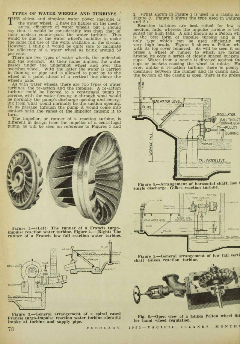
The impellor, or runner of a reaction turbine, is different in design from the impellor of a centrifugal pump, as will be seen on reference to Figures 1 and
2. (That shown in Figure 1 is used in a casing as Figure 3. Figure 2 shows the type used in Figures and 5.) Reaction turbines are best suited for low a: medium falls, whereas the impulse turbine is betl suited for high falls. A unit known as a Pelton win is the best form of impulse turbine and is t only type which can be used efficiently wi very high heads. Figure 6 shows a Pelton wh< with its top cover removed. As will be seen it co] prises a wheel or runner to which are fasten around its edge a series of closely spaced buckets cups. Water from a nozzle is directed against th( cups or buckets causing the wheel to rotate. Ho ever, unlike a re-action turbine, there is plenty clearance between the runner and its casing and, the bottom of the casing is open, there is no pressi
Figure 1.-(Left) The runner of a Francis turgo impulse reaction water turbine. Figure 2.-(Right) The runner of a Francis low fall reaction water turbine.
Figure 3.—General arrangement of a spiral cased Francis turgo-impulse reaction water turbine showing intake at turbine and supply pipe.
Figure 4.—Arrangement of horizontal shaft, low [?] single discharge, Gilkes reaction turbine.
Figure s.—General arrangement of low fall verti[?] shaft Gilkes reaction turbine.
Fig. 6.—Open view of a Gilkes Pelton wheel fit[?] for hand wheel regulation.
side it. The first of these two factors makes the ilton wheel the ideal machine for handling water lich carries silt or sand in suspension as there are i fine clearances to wear as is the case with a re tion turbine —and the extra weight of the sand tually does work!
Speed Control
OME form of speed control is necessary on water turbines unless the load is constant, such as with that provided by a centrifugal pump or a genera * charging batteries. They are unlike a steam or engine in this respect as the runaway speed of a iter turbine is usually not more than 80 per cent, ove its normal speed. Thus they would not race destruction as would be the case with an un irerned steam or oil engine if the load was removed, [ncidentaliy, speed control is very necessary when turbine is driving an alternator (AC generator) in ier to maintain the correct cycle, but it is not so cessary when operating a DC generator which is t working in parallel with other generators; an tomatic voltage regulator usually being sufficient to >p the voltage within reasonable limits.
With small hydro-electric sets the simplest form of reming is perhaps the electric brake. This cour ses a separate generator which imposes an arti ial load on the turbine, the extent of which varies accordance with the load of the main generator, r instance, if the turbine develops say, 15 hp and
the immediate load of the main generator is only equivalent to 10 hp, the electric brake governor will automatically present a load of 5 hp. This type of governor is suitable for both re-action and impulse turbines.
Another means of controlling the speed of a re action turbine is by means of a governor which con trols the amount of water allowed to enter it. This operates on a principle similar to that of a steam engine governor; revolving weights rise and fall to different positions according to the speed at which they are being driven.
A similar type of governor is used for impulse tur bines (i.e. Pelton and Turgo-impulse wheels), but in this case, instead of reducing or increasing the amount of water being directed to the wheels, the governor causes the jet or stream to be deflected.
Electrical Calculations
IN estimating the amount of current that can be ob tained from a given horsepower it is usual to allow for 1 hp to produce 500 watts. The theoretical electrical equivalent of 1 hp is 746 watts, but here again the loss-of-efiiciency factor has to be taken into consideration. With an electric generator the first loss is due to the friction in its bearings. Then comes its electrical losses. These make themselves evident by the heat which a generator produces within itself when working on load. (Continued Next Page)
Cost Of Hydro-Electric Plants
fITHE cost of a hydro-electric plant is somewhat X higher than that of an engine driven set of the same size, but it must be remembered that once installed the running costs of a hydro-electric plant are practically nil and its maintenance cost neglig ible. To give you some idea of the initial cost, how ever, I might mention that Coates & Co. Pty., Ltd., of 252 Swanston Street, Melbourne, and 302 Pitt Street, Sydney, which is the Australasian agent for Gilbert Gilkes & Gordon Ltd., water turbine and pump manufacturers, of Kendall, England, quotes a low fall vertical shaft propeller type turbine direct coupled to a 1,500 watt 230 volt D.C. generator and an electric brake governor complete with switchgear and meters all built into the one compact frame at about £650. On top of this is, of course, the cost of installation, including the earth and water works.
Measurement Of Head
AS in pumping, the total or net head available for power is the vertical height from the lowest water level in the tail race to the level of the water in the stream less the loss of head due to nipe friction, for it does not matter whether the water is being pumped or is flowing by gravity, the loss due to pipe friction is the same. For this reason the usual practice is to use pipe of a size in which friction is practically nil.
For small plants the friction table quoted on page
81 will suffice. From this you will get an idea of size pipe required.
Measurement Of Flow In Small Stream
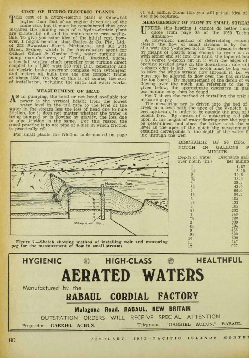
UNDER this heading I cannot do better than quote from page 35 of the 1950 Techn Annual:»— A convenient method of determining reasons closely the flow of small streams is by the of a weir and V-shaped notch. The stream is damr by means of boards long enough to reach acios with either end set into the bank, the topmost a 90 degree V-notch cut in it with the edges of opening levelled away on the downstream side so t a sharp edge is left. The notch must be big eno to take the whole stream flow through it, i.e., Wi must not be allowed to flow over the flat surface the top board. By measurement of the depth of wj flowing over the notch and reference to the ts given below, the approximate discharge in gal] per minute may then be found.
Fig. 7 shows the method of installing the weir ! measuring peg.
The measuring peg is driven into the bed of creek on a level with the apex of the V-notch, a feet upstream, in order to be outside the area of t bulent flow. By means of a measuring rod pla upon it, the height of water flowing over the peg i be determined, and since the latter is at the sj level as the apex of the notch the measurement obtained corresponds to the depth of the water fl ing through the weir.
Discharge Of 90 Deg.
Notch In Gallons P
Minute
Figure 7. —Sketch showing method of installing weir and measuring peg for the measurement of flow in small streams.
Depth of water Discharge gall over notch (in.) per minut* 1 1.87 11 5.15 2 10.6 21 18.5 3 29.2 34 43.0 4 60.0 44 80.5 5 105 5h 133 6 165 64 202 7 243 74 288 8 339 8£ 394 9 455 94 520 10 592 11 747 12 927